
What you’ll build (quick)
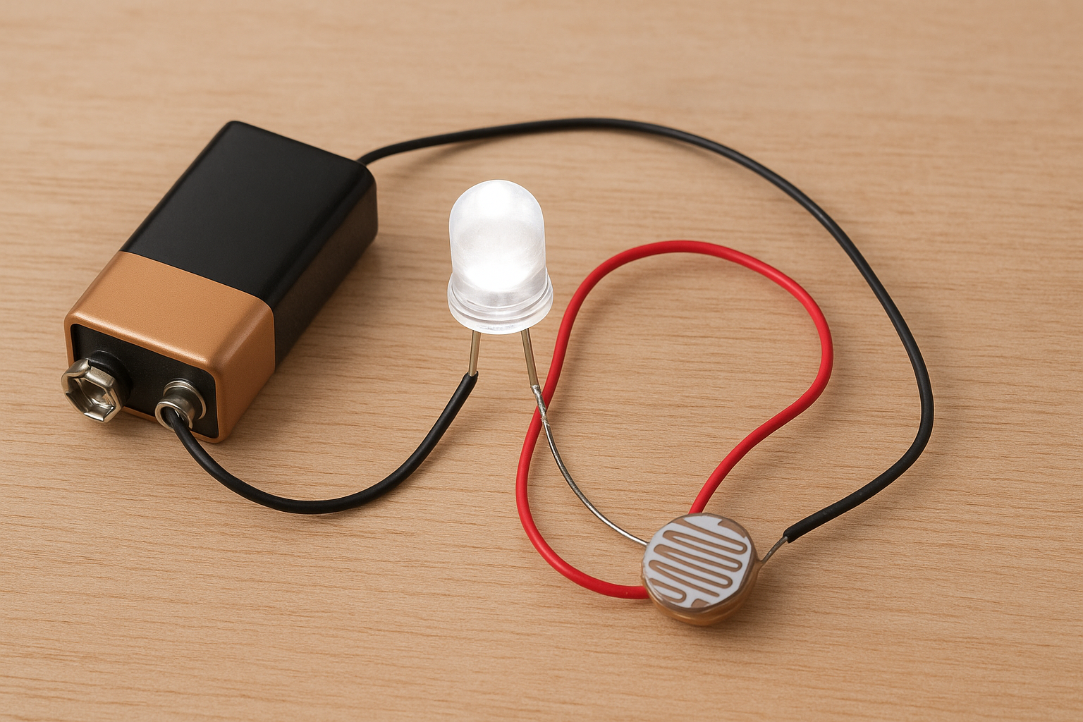
A compact, battery-powered automatic light using LDR that turns a single 1W LED ON when ambient light falls below a threshold (night) and OFF in daylight. The circuit uses an LDR as the light sensor and a small logic-level N-channel MOSFET as the switch to handle the LED current safely and efficiently. No microcontroller or mains wiring required.
Parts & Tools (affiliate link placeholders)
Core components
- 1 × 1W LED (white, 3V–3.3V forward voltage typical) — Buy on Amazon → [affiliate link]
- 1 × small logic-level N-channel MOSFET (e.g., IRLZ44N, IRLZ34, or better: AOZxxx logic MOSFET suitable for 3–6V gate) — Buy on Amazon → [affiliate link]
- 1 × LDR (photoresistor) — Buy on Amazon → [affiliate link]
- 1 × resistor for the LDR voltage divider (10k suggested) — Buy on Amazon → [affiliate link]
- 1 × battery (single Li-ion 18650 cell with protection / or 4×AA NiMH pack) — Buy on Amazon → [affiliate link]
- Breadboard + jumper wires — Buy on Amazon → [affiliate link]
Tools
- Multimeter — affiliate
- Soldering iron (if moving to perfboard) — affiliate
- Wire stripper/cutter _ affiliate
How the circuit works (simple)
We form a voltage divider with the LDR and a fixed resistor. That produces a voltage that changes with light level. The MOSFET gate reads this voltage: in darkness the divider voltage goes high enough to switch the MOSFET ON, allowing current to flow from the battery through the LED (and its current-limit resistor/driver). In daylight the divider voltage is low and the MOSFET remains off.
 — Simple DIY Guide")
This approach is efficient because the MOSFET handles LED current with low conduction losses and the LDR only needs to be a small sensor component. It’s far better than putting the LDR directly in series with the LED (which wastes sensor life and cannot safely handle 1W currents).
Two build options (choose one)
Recommended (simple & reliable) — LDR + MOSFET
Works well for a 1W LED, safe and efficient. Use appropriate gate resistor and a pull-down on the gate.
Component notes
- Rcurrent: sized to limit LED current or use a small constant-current module. For a 1W LED at ~350mA and Vf ≈ 3.2V, choose resistor value using P = I × Vdrop. Best practice: use a 350mA LED driver. If using a resistor: R = (BatteryVoltage − Vf_LED) / DesiredCurrent.
- Rgate: 100Ω recommended to reduce ringing.
- Gate pull-down resistor: 100k between gate and source ensures MOSFET stays off when the divider is floating.
Minimal (not recommended) — LDR in series
You can put the LDR in series with the LED so the LED dims with light, but:
- LDRs are not rated for high current; a 1W LED draws ~300–350mA, often more than a common LDR can safely handle.
- This creates unpredictable behavior, poor threshold control, and shorter LDR life.
If you insist on extreme simplicity, it will work with a very low current LED, but not recommended for 1W LEDs.
Step-by-step assembly & wiring (recommended MOSFET version)
Step 1- Prepare parts
Confirm LED forward voltage (Vf) and recommended current (check datasheet). Typical 1W LED: Vf ≈ 3.0–3.5V at 300–350mA.
Choose battery that provides slightly above Vf (e.g., 3.7V Li-ion single cell for direct drive with resistor, or 4.2V fully charged). If using 1× Li-ion, use a constant current driver or resistor sized for current.
Step 2- Build the LDR voltage divider
- Place the LDR between gate node and battery negative (GND).
- Connect a 10k resistor from battery positive to the gate node.
- At daylight, divider pulls gate low; in dark, gate voltage rises.
Step 3- Gate components
- Put a 100k resistor between gate and source (GND) as a pull-down.
- Put a 100Ω series resistor between divider output and MOSFET gate (Rgate).
Step 4- MOSFET & LED
- Connect MOSFET source to battery negative (GND).
- Connect MOSFET drain to the negative side of the LED circuit (i.e., low side switching).
- Connect LED positive to battery positive through a current-limit resistor or LED driver.
Step 5- Final checks
- Double-check polarity (LED, MOSFET pins). Use a multimeter.
- If everything looks right, power on and cover/uncover the LDR to test.
Testing & troubleshooting
- Polarity correct? (LED anode to +, cathode to MOSFET drain)
- Gate pull-down exists? (100k to ground)
- Gate voltage in dark > MOSFET Vgs(th)? If not, change divider ratio.
- Battery voltage under load stable? If low, use larger battery.
Power & battery considerations
- A 1W LED at 350mA will drain a typical 18650 (~2500mAh) in roughly (2500mAh / 350mA) ≈ 7 hours ideal (real is less due to driver inefficiencies).
- For longer runtime, use multiple cells or a bigger Li-ion pack, or reduce duty cycle with a light-only timer (e.g., add a small microcontroller later).
- Use battery protection (especially for Li-ion).
Safety notes
- This design is battery-powered only — do not connect to mains without an isolated driver or relay and proper knowledge.
- Use current limiting for the LED to avoid thermal runaway.
- If soldering, follow standard safety and ventilation practices.
FAQ & variations
Q: Can I power multiple 1W LEDs?
A: Yes — but scale the MOSFET rating and battery capacity. Use a proper constant-current driver for multiple LEDs.
Q: Can I replace MOSFET with a transistor?
A: Yes — a MOSFET is preferred due to lower losses. If you must use a BJT, pick one that can handle the current and provide base drive.
Q: Can I add a timer or dimmer?
A: Easily — add a small MCU (like Arduino Nano) or a simple 555 timer to add delays or dimming via PWM.
Conclusion
This simple LDR + MOSFET circuit is the fastest way to get a reliable automatic 1W LED night light running from a battery without microcontrollers. It’s efficient, compact, and safe for battery operation. If you want, I’ll also prepare:
- A printable schematic PNG (clean diagram) to embed inside the post, and
- The ready-to-paste HTML snippet with image tags and affiliate link placeholders already inserted.
Would you like me to:
A) Generate the clean schematic PNG now (I’ll produce and attach it), or
B) Produce the full 2000-word article in final formatted HTML including image tags, affiliate placeholders and the diagram embedded?
(If B, I’ll include both images and the full 2000-word formatted article so you can paste directly into your CMS.
Essential Tools for DIY Electronics Projects
Top 10 DIY Sensor-Based Projects for Students
How to Make a Battery Polarity Tester at Home – Simple DIY Circuit Guide