
What is Continuity Testing
Continuity Testing means checking if an electrical path is complete and broken ensuring electricity can flow with a positive result often being a beep or low resistance reading on a multimeter, confirming there are no breaks or faults in wires or circuits.
In simple terms:
What it is: Determining whether a circuit or wire is fully connected or not, or if there is a break or fault somewhere along the way.
How it’s done: Using a multimeter, which emits a beeping sound or shows a reading, to determine if current is flowing.
Why it’s done: Because it helps identify if a wire is broken, if a switch is working correctly, or if a connection in the circuit is properly made.
What is multimeter and how does it works?
A Multimeter is a digital versatile electronic tool that measures multiple electrical properties like Voltage (Volt), Current (amps), and Resistance (ohms), It combines all the functions of a voltmeter, ammeter, and ohmmeter, along with a digital display for easy reading. It’s an excellent tool for electricians, hobbyists, and technicians. It helps them identify faults, test components, and check the health of batteries in electrical systems and electronics.
Multimeter : (Amazon)
Read Full Blog Post : What is Multimeter and how does its works?
So guys, the above is a complete blog post about multimeters. In today’s blog, we are going to learn why continuity mode is useful.
Continuity mode is very essential in electrical work because it allows us to quickly and easily determine if an electrical path is intact or not.
When Should You Perform a Continuity Testing?
Checking wires and cables :
First, we need to set the meter to continuity or resistance mode, but before that, make sure the cable or wire is not connected to any power source. Then, place one probe of the multimeter on one end of the wire and the other probe on the other end. If the meter beeps or shows low resistance, then the wire is perfectly fine. If it doesn’t, it indicates that the wire is shorted or faulty.
Testing Fuses

To test fuses, first switch off the power or disconnect the circuit from the power source. Then remove the fuse from its holder. Next, set the multimeter to continuity mode (if continuity mode is not available, then set it to the lowest ohm setting). Then, place both probes of the multimeter on both ends of the fuse. If the fuse is Good, the multimeter will beep or show a reading of close to 0 ohms. If there is no beep or reading, or if it shows infinite or very high resistance, then the fuse needs to be replaced with a new one.
Verifying switches and relays
A multimeter can be employed to confirm the operation of switches and relays but one must power off the circuit first to ensure safety. Put the multimeter in continuity or resistance (ohm) mode and carry out a switch test by positioning the probes over the switch terminals.
The multimeter will indicate continuity (or minimal resistance) for the ON switch and no continuity (OL or maximal resistance) for the OFF switch. In the case of relays, measure the coil terminals for a given resistance (not OL or zero), then switch on the control voltage to the coil and check for continuity across the relay’s contact terminals—continuity will be there while the relay is active and not there while it is inactive.
Diagnosing an open circuit

To diagnose an open circuit, one has to locate the point of the electrical path break current. Start the process by switching off the power to the circuit and then take the multimeter to the continuity or resistance mode and check across the circuit path starting from the power source and moving toward the load. Measure each part of it- wires, connectors, switches, fuses, and components; a good path will indicate continuity or low resistance, whereas an open circuit will indicate no continuity or OL. After identifying the spot where the continuity is lost, check for broken wires, loose connections, damaged components, or blown fuses in that area and then repair or replace them as necessary.
Tools You’ll Need
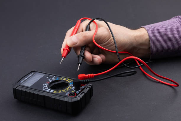
When it comes to checking electrical paths, fuses, switches, and connections, a digital multimeter (DMM) is essential. Two test leads (red/black) are also necessary. It is crucial that the power is off during testing. A continuity tester and wire cutters are also helpful to ensure smooth testing.
- Digital multimeter: A versatile instrument that provides information both visually and audibly when a closed circuit is detected.
- Test Leads: A multimeter comes with two probes (red and black) which make it easy to test any circuit.
- For Safety: Wire cutters, gloves, and alligator clips are also needed, as they will make the testing process easier.
Step-1
First and foremost, the power to the circuit being tested must be turned off. Otherwise, even a small mistake could result in an electric shock or completely damage the circuit.
Step-2
Connect the Test Leads: Connect the black lead to the COM (common) jack and the red lead to the VΩ or VΩmA jack. Do not use the “10A” or “A” jacks, as these are for high current measurements.
Step-3
Locate the Symbol: First, set the multimeter’s dial to the continuity symbol. It usually looks like a series of sound waves (→|).
Secondary Function: On many digital multimeters, continuity is a secondary function on the resistance (Ω) or diode setting. If you see this symbol shared with other functions on your multimeter, you will often need to press the “Select,” “Mode,” or “Function” button until the sound wave icon appears on the digital display.
Step-4
Test the Tester: If the connection is correct, touching the metal tips of both probes together will produce a continuous beep, and the display will show a reading close to 0 ohms.

safety tips for continuity testing
- Always turn off and disconnect power before performing continuity testing.
- Never test continuity on a live or energized circuit.
- Discharge capacitors to prevent stored electrical energy.
- Set the multimeter to the correct continuity mode before testing.
- Inspect test leads for damage or exposed wires.
- Hold probes by the insulated handles only.
- Ensure proper contact between probes and test points.
- Test the multimeter on a known working circuit first.
- Avoid continuity testing on sensitive electronic components unless specified.
- Keep your hands dry and work in a safe, dry environment.
Continuity Testing vs Resistance Testing:
Continuity testing and resistance testing are two significant functions of a multimeter that are applied in the electrical troubleshooting process, however they have different roles. Continuity testing is an instant pass or fail test that shows whether a circuit path is complete or not, usually a beep is heard when the resistance is at an extremely low level. This is the case for wires, fuses and switches where it is sufficient to know if current can flow through.

Resistance testing, conversely, gives the precise value of resistance in ohms making it more appropriate for the diagnosis of components like resistors, coils, or wires that have been affected by partial damage. While continuity testing emphasizes speed and convenience, resistance testing gives more in-depth information for further investigation, and both are typically used together for precise fault finding.
Conclusion:
Continuity testing is a fundamental electrical measurement used to determine if there is a continuous current path between two points. This test helps in troubleshooting components such as fuses and switches, identifying broken wires, and detecting short circuits in new circuit boards and PCBs.
The continuity testing skill goes hand in hand with time-shaving, as its offering of a quick, efficient, and precise method for diagnosing electrical faults down to their exact location won’t let an operator rotate through guesses nor spend money on unnecessary repairs caused by faults in the guessing process.
Read more Guide to Buy a Multimeter: Top 5 Digital Multimeters